After designing and building a new router, I initially used UGS (Universal GCode Sender) with an Arduino running GRBL. While it worked well most of the time, I occasionally encountered issues—UGS would lose keyboard control while the tool was moving, leading to botched jobs and even broken tools. That was enough frustration for me to switch to Mach3.
I have a licensed copy of Mach3 that I previously used with an old CNC milling machine. However, my version was designed for 32-bit Windows 7 and communicated via a parallel printer port. To use Mach3 with my new router, I needed to transition to 64-bit Windows 11 and establish communication over USB.
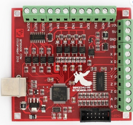
Upgrading Mach3 for this setup was costly, so I decided to try the BSMCEO4U-PP board, which enables Mach3 to communicate with the router via USB without requiring additional drivers. I found the board on Amazon for £16.45 and decided to give it a shot.
USB motion control card – First thoughts
At first, panic set in—the documentation was only available on a CD, and I didn’t have a CD reader. I took a USB memory stick and the CD to a friend, who helped me copy the contents onto the stick.
Crisis averted— or was it? Most of the documentation for the BSMCEO4U-PP card was in Chinese, making it nearly useless to me.
Thankfully, after a bit of googling, I found this:
Installation. Order of business
I installed the BSMCEO4U-PP card, set up Mach3, and added my license. Here’s the procedure I followed:
- Backup Important Settings
- If upgrading from an existing Mach3 installation, note the current ‘Motor Tuning’ settings for X, Y, and Z—only steps and acceleration matter.
- Secure a copy of your existing
Mach1Lic.datfile.
- Install Mach3
- Follow the instructions in the manual (see link above) to install Mach3 from the media supplied with the board. Ensure you use the version compatible with Windows 10 or Windows 11. Alternatively, download the correct version online.
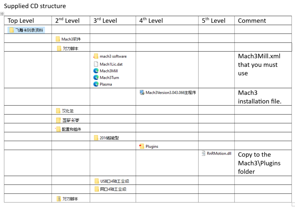
- File locations on the CD are listed below.
- Copy Essential Files
- Copy the
Mach3Mill.xmlfile from the CD into the Mach3 folder (default:C:\Mach3). Do not reuse an existing Mach3Mill.xml file. - Move the Mach3 plug-in (
RnRMotion.dll) from the CD into theMach3\Pluginsfolder. - Transfer your
Mach1Lic.datfile to the Mach3 folder.
- Copy the
- Configure Mach3
- Start Mach3 and select the new plugin. Note that the displayed name may differ from the actual file name—for me,
RnRMotion.dllappeared as “BS Motion Control…”. Be sure to select “Don’t ask me this again.” - Restore your ‘Motor Tuning’ settings using the values recorded earlier.
- Start Mach3 and select the new plugin. Note that the displayed name may differ from the actual file name—for me,
With Mach3 installed, I moved on to wiring everything up—starting with the spindle.
Wiring up the spindle
This is where I encountered my biggest challenge—I wanted to use Mach3’s capability to control the spindle via the BSMCEO4U-PP OUT1 pin. I opted for a simple relay-controlled setup, but to do this, I needed a 24V power source, which is the maximum allowed through the OUT1 pin.
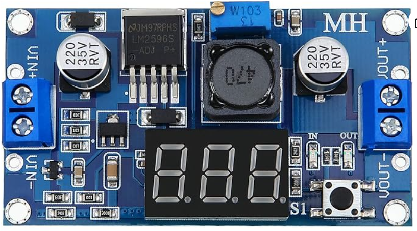
My existing power supply outputs 36V, so I had to integrate a buck converter to step the voltage down from 36V to 24V. The buck converter I used is based on the LM2596 DC-DC model, which I purchased from Amazon for £6.99. Its digital display made voltage adjustment straightforward, allowing me to fine-tune the output to exactly 24V.
While there are buck converters without a digital display, adjusting the output voltage on those requires a multimeter.
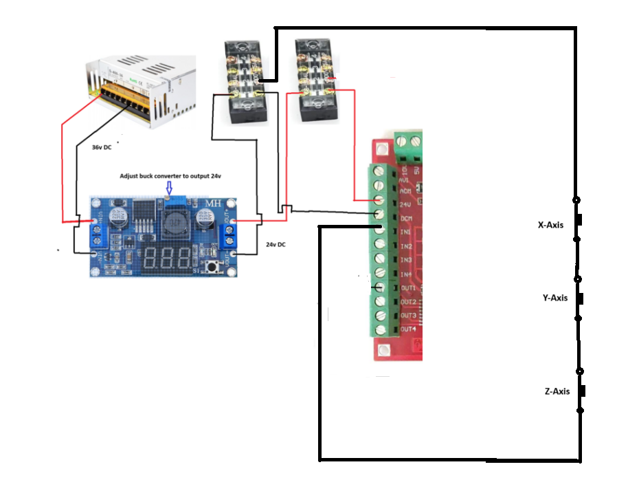
The buck converter was wired to the BSMCEO4U-PP board as illustrated below.
Initially, I connected the low-voltage side of the relay directly to the OUT1 pin without a resistor or diode, which resulted in the OUT1 circuit blowing.
To prevent this from happening again, I am now using a 2.2kΩ resistor to limit the current sinking to the OUT1 pin (see below). Hopefully, this setup will work.
I’ll run some tests and report back once I have more results.
Update: After running the spindle for a few days, everything seems to be working well. In hindsight, I should have paid closer attention to the documentation (link above), which states that the ULN2003 Darlington array allows a sink current of 60mA, even though its datasheet indicates it can handle up to 500mA.
I’m counting on the 2.2kΩ resistor to do the job.
Now, for the technical breakdown (and feel free to correct me if I’m off here): Using Ohm’s Law (V = IR), we find that: I = V/R → 24V / 2200Ω = 10.9mA
The SSR-25 requires 7.5mA to trigger, so a 2.2kΩ resistor should be sufficient.
.

Wiring the Stepper motors
With spindle control sorted, I moved on to wiring the stepper motor controllers. The wiring process is outlined in the documentation available via the link above.
To wire the stepper motors:
- Connect the X, Y, and Z pul+ and dir+ pins to the XD, XP, YD, YP, ZD, and ZP pins on the USB board.
- Use a common ground from the GRN pin to wire the pul- and dir- pins.
- Important: Do not connect the pul- and dir- pins to the DCM pin, as this pin is part of the 24V supply.
For the X-axis, I use two opposing stepper motors.
- One motor connects to XD and XP, while the other is wired to AD and AP on the BSMCEO4U-PP board.
- To keep both motors in sync, I used Mach3’s slave settings to map the A axis to X.
With the stepper motors configured, I moved on to wiring the limit switches.
Wiring the Limit switches
I wired my limit switches as a series of normally closed switches. While this setup doesn’t allow Mach3 to determine which specific axis has been limited, my primary concern is simply stopping the machine when it reaches a limit.
Assuming the 24V and DCM pins on the BSMCEO4U-PP have been wired as described in the spindle wiring, here is the circuit I used:
Mach3 Ports and Pins settings for the limit switches

Notice that the X++ and X– is the only limit axis used. As all the switches are wired in series it would not have mattered which of the axes was used.
File locations on the supplied media